RDNA3#
ROCm Compute Profiler makes available an extensive list of metrics to better understand achieved application performance on RDNA3.5 architecture-based AMD Ryzen™ APUs like AMD Ryzen AI Max / Ryzen AI Max+ Series (gfx115x).
To best use the profiling data, it’s important to understand the role of various hardware blocks of AMD RDNA3 architecture. Refer to the following top-level block diagram to understand the hardware blocks of RDNA3 architecture.
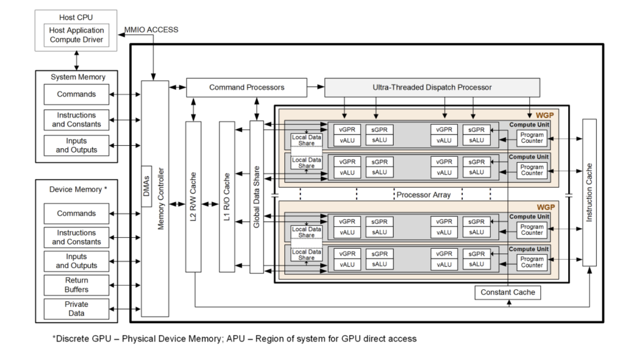
For more details on AMD RDNA3 architecture, see page 5 of RDNA3 shader instruction set architecture.
Note
For top-level metrics details on CDNA and RDNA architecture, see Performance model.
For details on metrics available for CDNA-CDNA4 architecture-based Instinct GPUs, see AMD CDNA architecture (CDNA-CDNA4).
For details on packaging, SIMD width, and generational differences between RDNA3, RDNA3.5, and later APUs, refer to GPU hardware specifications and the public architecture summaries.
ROCm Compute Profiler includes analysis panels targeting RDNA3.5 parts reporting as gfx115x, such as, integrated graphics on AMD Ryzen AI Max Series processors.
Memory hierarchy in the tool#
For gfx115x, the Memory Chart panel walks the path from instruction and scalar paths, GL0 (TCP), LDS, interfaces to GL1 Cache, GL2 Cache, and GCEA toward system memory.
Workgroups and execution#
RDNA3 architecture-based APUs organize compute around Workgroup Processors (WGPs) and Compute Units (CUs). On gfx115x, each WGP pairs two CUs that share resources. Wavefronts are typically wave32 oriented in this configuration. The WGP, Shader Processor Input (SPI), and Command Processor Compute (CPC) panels in gfx115x expose dispatch, occupancy, and command-processor metrics for this RDNA execution model (see the sub-sections under Shader engine and Command processor (CP)).
Hardware blocks#
The ROCm Compute Profiler documentation follows the RDNA3 gfx115x block hierarchy below:
Shader engine#
Within each shader engine, gfx115x metric tables are grouped under:
Workgroup Manager (SPI): Schedules wavefronts onto WGPs after the command processor dispatches work. Tracks SPI utilization and wave-dispatch statistics.
Workgroup processor (WGP): CU-pair execution (occupancy, waves, instruction mix, and WGP instruction/data caches).
GL0 (TCP Vector Cache): Vector L0 immediately before GL1; TCP-named counters through the TCP-GL1 boundary.
GL1: Shared L1 utilization, requests, cache performance, and the GL1-GL2 interface.
For more details, see Shader engine.
Last-level cache and memory paths#
GL2 cache: Last-level GFX on-chip cache performance, requests, and bandwidth.
Graphics Core Efficiency Arbiter (GCEA): DRAM read/write interfaces, system arbiter (SARB), and return traffic after GL2.
Host-side control and coarse utilization#
Command processor (CP): CPC/MEC panels from packet handling through dispatch toward SPI.
Graphics Register Bus Manager (GRBM): GPU-wide and per-shader-engine utilization from GRBM-derived counters.
Additional reference material#
System Speed-of-Light: System Speed-of-Light table using the same gfx115x metric keys as the analysis panel.
References: Public references and links to complementary Instinct documentation.
Note
ROCm Compute Profiler currently has limited support for WMMA on gfx115x.