AMD Instinct™ MI100 microarchitecture#
2025-10-31
6 min read time
The following image shows the node-level architecture of a system that comprises two AMD EPYC™ processors and (up to) eight AMD Instinct™ GPUs. The two EPYC processors are connected to each other with the AMD Infinity™ fabric which provides a high-bandwidth (up to 18 GT/sec) and coherent links such that each processor can access the available node memory as a single shared-memory domain in a non-uniform memory architecture (NUMA) fashion. In a 2P, or dual-socket, configuration, three AMD Infinity™ fabric links are available to connect the processors plus one PCIe Gen 4 x16 link per processor can attach additional I/O devices such as the host adapters for the network fabric.
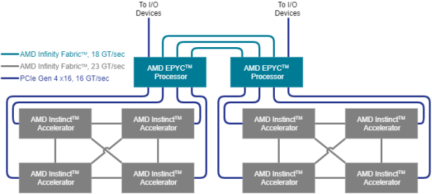
In a typical node configuration, each processor can host up to four AMD Instinct™ GPUs that are attached using PCIe Gen 4 links at 16 GT/sec, which corresponds to a peak bidirectional link bandwidth of 32 GB/sec. Each hive of four GPUs can participate in a fully connected, coherent AMD Instinct™ fabric that connects the four GPUs using 23 GT/sec AMD Infinity fabric links that run at a higher frequency than the inter-processor links. This inter-GPU link can be established in certified server systems if the GPUs are mounted in neighboring PCIe slots by installing the AMD Infinity Fabric™ bridge for the AMD Instinct™ GPUs.
Microarchitecture#
The microarchitecture of the AMD Instinct GPUs is based on the AMD CDNA architecture, which targets compute applications such as high-performance computing (HPC) and AI & machine learning (ML) that run on everything from individual servers to the world’s largest exascale supercomputers. The overall system architecture is designed for extreme scalability and compute performance.
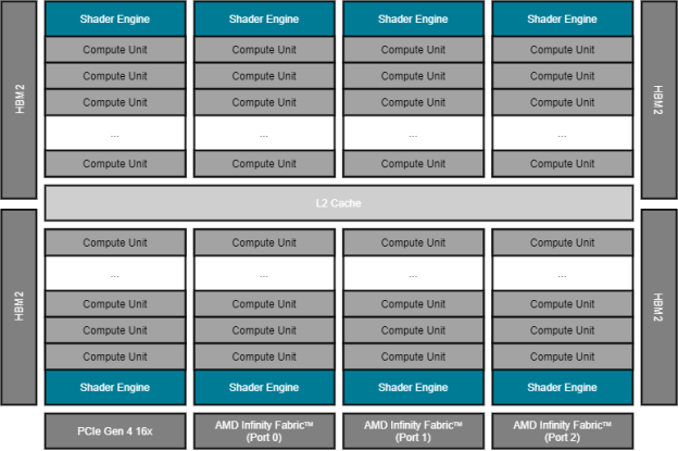
The above image shows the AMD Instinct GPU with its PCIe Gen 4 x16 link (16 GT/sec, at the bottom) that connects the GPU to (one of) the host processor(s). It also shows the three AMD Infinity Fabric ports that provide high-speed links (23 GT/sec, also at the bottom) to the other GPUs of the local hive.
On the left and right of the floor plan, the High Bandwidth Memory (HBM) attaches via the GPU memory controller. The MI100 generation of the AMD Instinct GPU offers four stacks of HBM generation 2 (HBM2) for a total of 32GB with a 4,096bit-wide memory interface. The peak memory bandwidth of the attached HBM2 is 1.228 TB/sec at a memory clock frequency of 1.2 GHz.
The execution units of the GPU are depicted in the above image as Compute
Units (CU). There are a total 120 compute units that are physically organized
into eight Shader Engines (SE) with fifteen compute units per shader engine.
Each compute unit is further sub-divided into four SIMD units that process SIMD
instructions of 16 data elements per instruction. This enables the CU to process
64 data elements (a so-called ‘wavefront’) at a peak clock frequency of 1.5 GHz.
Therefore, the theoretical maximum FP64 peak performance is 11.5 TFLOPS
(4 [SIMD units] x 16 [elements per instruction] x 120 [CU] x 1.5 [GHz]).
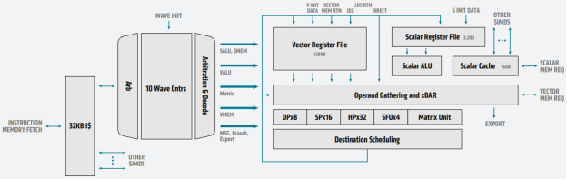
The preceding image shows the block diagram of a single CU of an AMD Instinct™ MI100 GPU and summarizes how instructions flow through the execution engines. The CU fetches the instructions via a 32KB instruction cache and moves them forward to execution via a dispatcher. The CU can handle up to ten wavefronts at a time and feed their instructions into the execution unit. The execution unit contains 256 vector general-purpose registers (VGPR) and 800 scalar general-purpose registers (SGPR). The VGPR and SGPR are dynamically allocated to the executing wavefronts. A wavefront can access a maximum of 102 scalar registers. Excess scalar-register usage will cause register spilling and thus may affect execution performance.
A wavefront can occupy any number of VGPRs from 0 to 256, directly affecting occupancy; that is, the number of concurrently active wavefronts in the CU. For instance, with 119 VGPRs used, only two wavefronts can be active in the CU at the same time. With the instruction latency of four cycles per SIMD instruction, the occupancy should be as high as possible such that the compute unit can improve execution efficiency by scheduling instructions from multiple wavefronts.
Computation and Data Type |
FLOPS/CLOCK/CU |
Peak TFLOPS |
|---|---|---|
Vector FP64 |
64 |
11.5 |
Matrix FP32 |
256 |
46.1 |
Vector FP32 |
128 |
23.1 |
Matrix FP16 |
1024 |
184.6 |
Matrix BF16 |
512 |
92.3 |