Understanding the HIP programming model#
The HIP programming model makes it easy to map data-parallel C/C++ algorithms to massively parallel, wide single instruction, multiple data (SIMD) architectures, such as GPUs. A basic understanding of the underlying device architecture helps you make efficient use of HIP and general purpose graphics processing unit (GPGPU) programming in general.
RDNA & CDNA Architecture Summary#
Most GPU architectures, like RDNA and CDNA, have a hierarchical structure. The innermost piece is a SIMD-enabled vector Arithmetic Logical Unit (ALU). In addition to the vector ALUs, most recent GPUs also house matrix ALUs for accelerating algorithms involving matrix multiply-accumulate operations. AMD GPUs also contain scalar ALUs, that can be used to reduce the load on the The innermost piece is a SIMD-enabled vector Arithmetic Logical Unit (ALU). In addition to the vector ALUs, most recent GPUs also house matrix ALUs for accelerating algorithms involving matrix multiply-accumulate operations. AMD GPUs also contain scalar ALUs, that can be used to reduce the load on the vector ALU by performing operations which are uniform for all threads of a warp.
A set of ALUs, together with register files, caches and shared memory, comprise a larger block, often referred to as a compute unit (CU), e.g. in OpenCL and AMD block diagrams, or as streaming multiprocessor (SM).

Fig. 1 Block Diagram of an RDNA3 Compute Unit.#

Fig. 2 Block Diagram of a CDNA3 Compute Unit.#
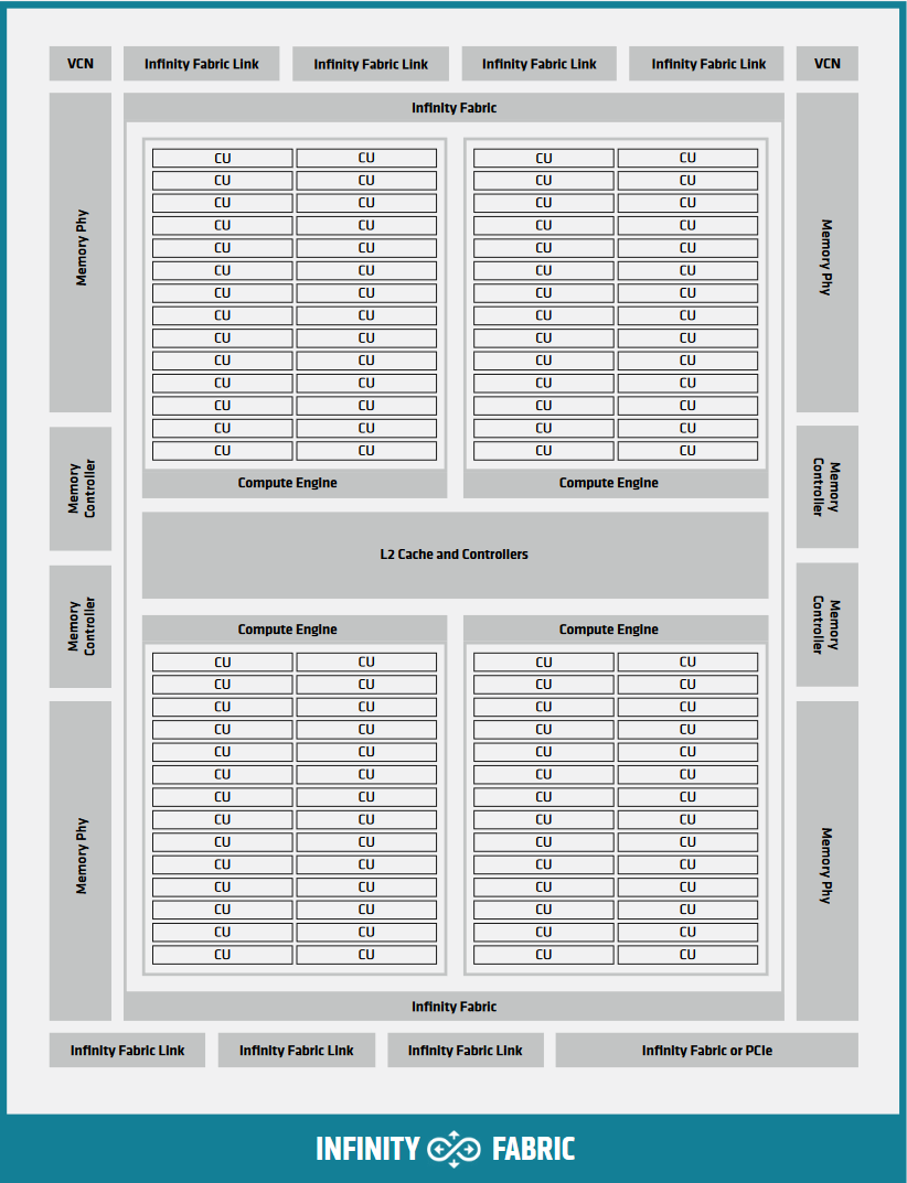
For implementation in hardware, multiple CUs are grouped together into a Shader Engine or Compute Engine, typically sharing some fixed function units or memory subsystem resources.

Fig. 3 Block Diagram of a CDNA2 Graphics Compute Die.#
Single Instruction Multiple Threads#
The single instruction, multiple threads (SIMT) programming model behind the HIP device-side execution is a middle-ground between SMT (Simultaneous Multi-Threading) programming known from multicore CPUs, and SIMD (Single Instruction, Multiple Data) programming mostly known from exploiting relevant instruction sets on CPUs (for example SSE/AVX/Neon).
A HIP device compiler maps SIMT code written in HIP C++ to an inherently SIMD architecture (like GPUs). This is done by scalarizing the entire kernel and issuing the scalar instructions of multiple kernel instances to each of the SIMD engine lanes, rather than exploiting data parallelism within a single instance of a kernel and spreading identical instructions over the available SIMD engines.
Consider the following kernel:
__global__ void k(float4* a, const float4* b)
{
  int tid = threadIdx.x;
  int bid = blockIdx.x;
  int dim = blockDim.x;

  a[tid] += (tid + bid - dim) * b[tid];
}
The incoming four-vector of floating-point values b is multiplied by a
scalar and then added element-wise to the four-vector floating-point values of
a. On modern SIMD-capable architectures the four-vector ops are expected to
compile to a single SIMD instruction. GPU execution of this kernel however will
typically look the following:
Fig. 4 Instruction flow of the sample SIMT program.#
In HIP, lanes of a SIMD architecture are fed by mapping threads of a SIMT
execution, one thread down each lane of a SIMD engine. Execution parallelism
usually isn’t exploited from the width of the built-in vector types, but via the
thread id constants threadIdx.x, blockIdx.x, etc. For more details,
refer to Inherent Thread Model.
Heterogeneous Programming#
The HIP programming model assumes two execution contexts. One is referred to as
host while compute kernels execute on a device. These contexts have
different capabilities, therefor slightly different rules apply. The host
execution is defined by the C++ abstract machine, while device execution
follows the HIP model, primarily defined by SIMT. These execution contexts in
code are signified by the __host__ and __device__ decorators. There are
a few key differences between the two:
The C++ abstract machine assumes a unified memory address space, meaning that one can always access any given address in memory (assuming the absence of data races). HIP however introduces several memory namespaces, an address from one means nothing in another. Moreover, not all address spaces are accessible from all contexts.
If one were to look at Block Diagram of a CDNA2 Graphics Compute Die. and inside the Block Diagram of a CDNA3 Compute Unit., every Compute Unit has an instance of storage backing the namespace
__shared__. Even if the host were to have access to these regions of memory, the performance benefits of the segmented memory subsystem are supported by the inability of asynchronous access from the host.Not all C++ language features map cleanly to typical device architectures, some are very expensive (meaning slow) to implement on GPU devices, therefor they are forbidden in device contexts to avoid users tapping into features that unexpectedly decimate their program’s performance. Offload devices targeted by HIP aren’t general purpose devices, at least not in the sense a CPU is. HIP focuses on data parallel computations and as such caters to throughput optimized architectures, such as GPUs or accelerators derived from GPU architectures.
Asynchrony is at the forefront of the HIP API. Computations launched on the device execute asynchronously with respect to the host, and it is the user’s responsibility to synchronize their data dispatch/fetch with computations on the device. HIP does perform implicit synchronization on occasions, more advanced than other APIs such as OpenCL or SYCL, in which the responsibility of synchronization mostly depends on the user.